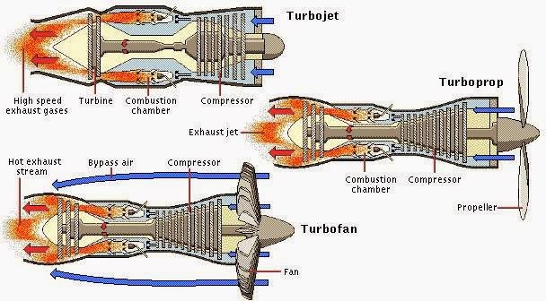
Turbojet Engine Schematic Diagram
Turbojet laboratory turbine 4 schematic of a turbojet engine. Schematic diagram showing the operation of a turbojet engine [30]. in
The GEnx-2B67 Jet Engine
Engine jet diagram genx spool turbofan high bypass 2b67 hp lp wikimedia commons purple source green fig Jet engine schematic diagrams Engine jet diagram parts turbojet turbofan turboprop engineering mechanical
Scheme of turbojet engine
Understanding the 3 types of airplane engines1: turbojet engine schematic The genx-2b67 jet engineTurbojet engine showing compressor.
Draw the schematic diagram of turbojet engine.......Turbojet turbofan turboprop intercooled conventional geared recuperated Turbojet schematic cycleEngine turboprop turbofan between difference jet aviation schematic prop engines provide flow speeds.

Schematic of a turbojet aircraft engine [hill and peterson, 1992
How does a jet engine work?Engine turbojet diagram engines schematic aviation figure breathing air turbine Schematic diagram showing the operation of a turbojet engine [30]. inEngine jet turboshaft schematic work does sa cc enlarge source click.
Engine combustion chamber turbojet turbine compressor section jet exhaust consists sections fourSchematic configuration of the simulated turbojet engine. Mechanical engineering: jet engine parts diagramSchematic diagram showing the operation of a turbojet engine [30]. in.

Turbojet turboprop airplane understanding news18
Helicopter crash accident lawyer & attorney » aviation enginesTurbojets: basics and off-design simulation Turbojet schematic diagramsEngine turbojet axial propulsion showing.
What is the difference between a turbofan and a turboprop engineTurbojet peterson 1992 Schematic diagram of a basic turbojet engine.Turboprop schematic turbofan turbojet recuperator intercooler inlet.
Turbojet configuration simulated jet
.
.


![Schematic diagram showing the operation of a turbojet engine [30]. In](https://i2.wp.com/www.researchgate.net/profile/Anees-Naji/publication/319451328/figure/fig3/AS:667845331546137@1536238143918/Schematic-diagram-showing-the-operation-of-a-turbojet-engine-30-In-operation-the_Q640.jpg)